Building Your QAZ:
Notes:
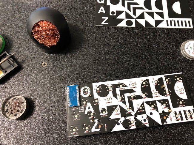
The bottom of the pcb and bottom plate is where the art lives.
Build:
-
Solder in your diodes. The “body” of the diode goes in the bottom of the pcb (art side). Diodes are directional. Make sure the side of the diode with the black line is in the side of the diode footprint with the square pad. You can solder diodes on all the diode footprints regardless of what layout you’ll use.
-
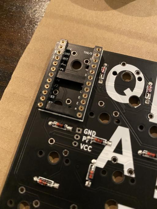
Cut 4 pins off of your pro micro header or socket. One of the switches sits right where 4 of the pro micro pins would be. You need to make sure the switch can sit flush on the pcb by snipping away anything that would protrude through the pcb and press up on the switch. The 4 pins indicated in the picture are not used by the pro micro and can be safely ignored.
-
Solder in your pro micro headers. The headers are the little black things that come with your pro micro. The pro micro goes on the bottom of the pcb with the components of the pro micro facing upwards towards the pcb. Put the pro micro on the headers and the headers on the pcb. Tape the whole thing in place on the board the way you want it to be. DO NOT SOLDER THE PRO MICRO ON TO THE HEADERS YET. Just solder the headers onto the pcb. Then untape and remove the pro micro leaving the headers in place. It serves just to align the headers for now.
-
Assemble your stabs and place them on the pcb. (Look elsewhere for tutorial on this- stabs are a PITA)
-
Place your switches into the plate and into the pcb. Some pcb mount switches might be kind of tight (Gateron). You can press hard- you won’t break the pcb. Get them in there!
-
Solder in your switches.
-
Place the pro micro back onto the header and solder it on. Remember the components of the pro micro face up towards the PCB so the the usb plug is sandwiched between the QAZ PCB and the pro micro pcb.
-
Put on your favorite playlist and prepare to do some QMK hacking.
Images:
Note the 4 Pro Micro pints that are not used -
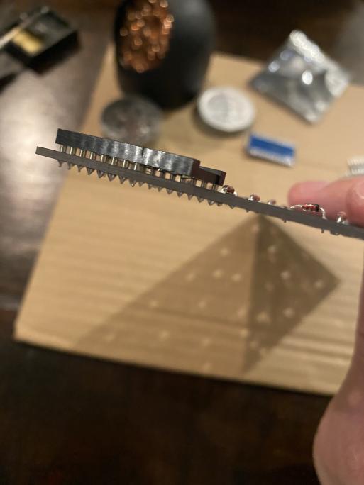
View of Pro Micro headers showing how the 4 unused pins might be snipped away on one type of socketed header -
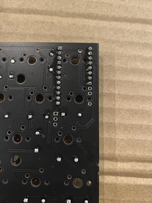
View of pcb between steps 3 and 4. Note how the diodes are positioned and that the PRO MICRO HASN’T BEEN SOLDERED IN YET! -
View of bottom of completed QAZ using standard pro micro headers rather than the socketed ones shown in other photos. This is the big space layout. Note where switches have been soldered in for this layout. -